SD-BD-04-02/Rev.05/15-01-67

ANNUNCIATOR SYSTEM (03 SERIES)
ANNUNCIATOR SYSTEM (03 SERIES)
Description
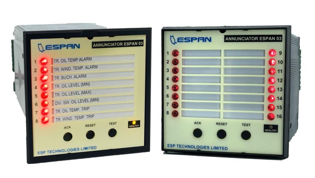
ESPAN – 03 series is designed to use as an alarm for general switchgear cubicle or local control panel of GIS, local control cabinet of power transformer and all of control panel, which need alarm function. It indicates fault status by using special high brightness LED. The ESPAN – 03 series can be selected by the number of alarm input 8 alarm or 16 alarm which specified when order.
Features
• DIN format 96 x 96 mm.
• Large space savings on the front panel of the cabinet.
• Built-in three push buttons for acknowledge/reset/test
• The label is a single paper sheet which slides into a small transparent envelope recessed in the front panel.
• All inputs are isolated with opto – couple NO or NC volt-free contact can be selected by software.
• Alarm sequences (auto/manual reset/indicator) of each input can be selected by software.
• Alarm type (bell/buzzer) of each input can be selected by software.
• High brightness LED display (5 mm.)
• Integrated two test functions (Lamp Test / Function Test) in only one push button (“TEST”)
• Auto acknowledge function time can be set from 1 – 240 seconds.
• Direct power supply 24, 48, 110, 125, 220, 230VDC. (specify when order also same as fault input voltage)
• Built-in heart beat function by LED lamp to display healthy status as self-supervision function.
• Supervisory contact (watchdog) for remote alarm or warning status.
• Communication port: RS232
Option
• DIN format 96 x 96 mm.
Technical Data

Operating Principle
When an alarm signal is occurred, it will initiate bell/buzzer to operate. In the meantime, it will produce output direct to the display LED, which makes LED flicking. After pressing an acknowledged push button, bell or buzzer remains silence but LED is steady on. If an alarm signal is return to normal status then the alarm is cancelled. However, the light of the indicating display LED will be sustained. Unless the reset push button switch is activated. Then the LED will be turn off and return to its initial condition. The “TEST” push button included two functions. The first function is “Lamp TEST” if push and hold this push button less than 3 seconds, it will light up all LED lamp at the front panel only. The second function is “Function test” if push and hold this push button more than 3 seconds, the LED lamp will start flicking and bell/buzzer alarm. This “TEST” push button is provided for the purpose of checking all LED and operating function at normal condition. While checking all LED and suddenly some of the alarm signals are occurred, the alarm sequence will be operated as usual without effect from the lamp test sequence. Alarm sequence can be selected by software for manual reset sequence or auto reset sequence, which described as below:
SEQUENCE1: MANUAL RESET
When an alarm signal is occurred, the LED would gently flash and bell or buzzer will activate continuously. To stop the sound of bell or buzzer, “ACK” push button has to be pressed. Then bell/buzzer is silenced but LED is still steady on. Reset is only possible by “RESET” push button when alarm input returns to normal status.
SEQUENCE2: AUTO RESET
When an alarm signal is occurred, the LED would gently flash and bell or buzzer will activate continuously. To stop the sound of bell or buzzer, “ACK” push button has to be pressed. Then bell/buzzer is silenced but lamp is steady on. Auto reset will take place when alarm input returns to normal status.
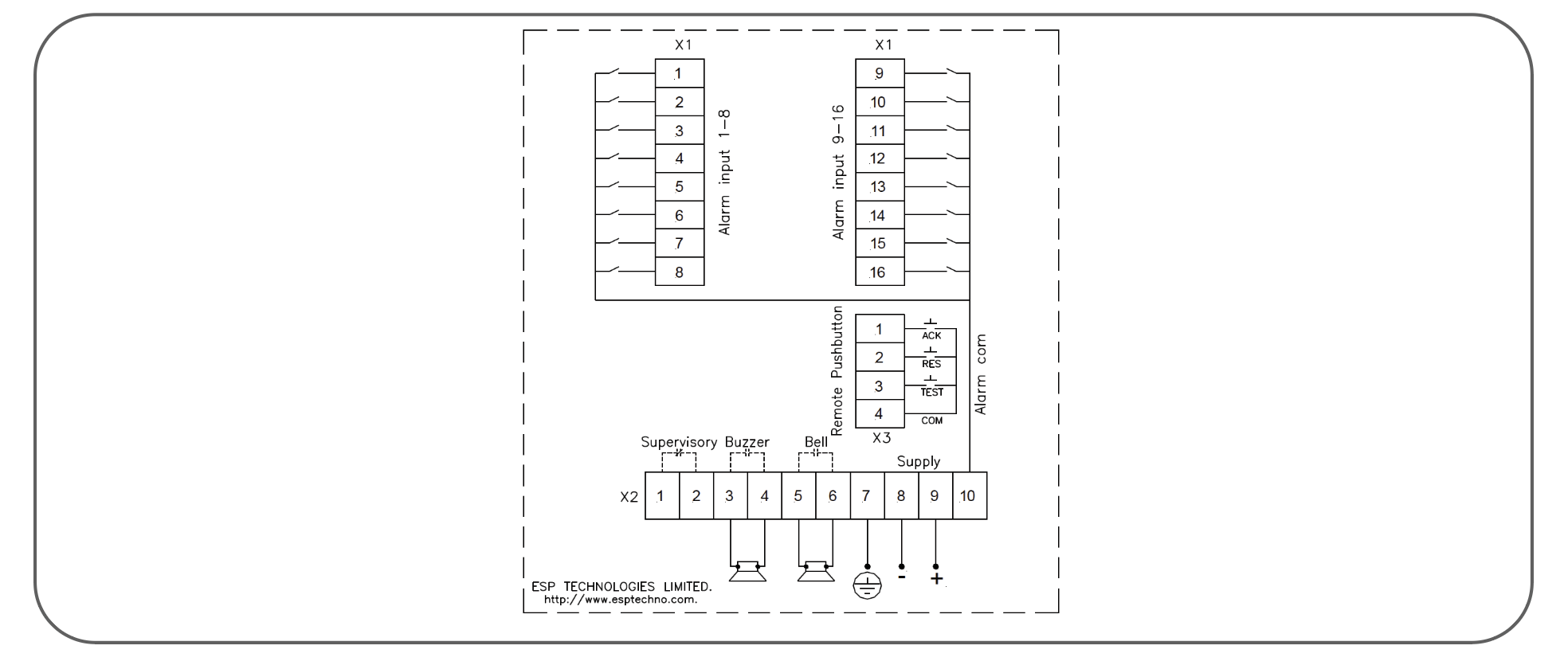
Connection Diagram

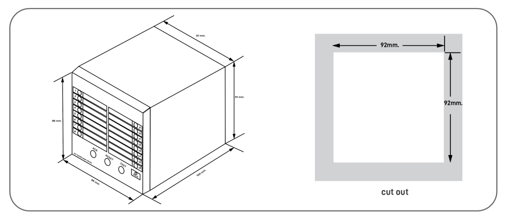
Dimension and Cutout

Product Coding


