ANNUNCIATOR SYSTEM (01 SERIES)
SD-BD-04-02/Rev.05/15-01-67

ANNUNCIATOR SYSTEM (01 SERIES)

Features
• Robust and compact design
• Space problem solving by separate into three modules; Master module/Extension module/Relay module
• The three modules are connected by detachable wire connector
• Sequence control push button switches are separated as given design on control panel
• All input channels are opto-isolator designed concept
• Alarm input contact can be selected by software to accept either NO or NC contact
• Alarm sound can be selected to be bell or horn (Heavy fault) and buzzer (Light fault) by software
• Number of alarms : 8, 16 to 64 alarms per one set of alarm sequence unit (Maximum is 640 alarms)
• Number of I/O of master module is 16 I/O per module (Surface mount type only) , Extension module is 8 I/O per module and relay output module is 8 NO contacts per module
• Supervisory contact (Watchdog) for remote alarm or warning status.
• Easily could be programmed with the belonging software (ESPAN01 V1.0) connected via USB port to computer
• Communication port : USB and RS485 modbus RTU protocols (Option : optical port)
• Lay out of display window is flexible according to the requirement
• Power supply : 24VDC (~50 watt for 16 alarms, ~100 watt for 32 alarms, ~150 watt for 64 alarms)
• Protection class : IP55 for display window and IP50 for alarm sequence unit (Master mudule + Extension mudule)
• Ambient temperature : -10 to +55°C
• Storage temperature : +70°C
• Humidity : up to 95%
Technical data
Alarm sequence unit
This unit is a combination module that starting from 16 to 64 alarm points using microprocessor base concept. When the fault signal occurs through an opto-isolator input channel, it will send flicker output (Open collector type) toward the visual device (Display window) and audible device such as bell or buzzer. The main features of this module are as below;
• This alarm sequence unit can accept fault signal DC 24/48V or DC 110/125V which powered through field contact.
• Flicker output can be adjustable and fault input signal can be adjust delay time by software.
• The alarm sequence units are 16, 24, 32, 40, 48, 56 and 64 alarm type.
• This unit can select bell or horn as a heavy fault and buzzer as a light fault by program software for each alarm point.
• Input alarm contact shall be either normally open (NO) or normally closed (NC) contact which can be selected by program software.
• Connection between modules equipped with detachable wire connector (RJ11 and pair connector)
Power supply unit
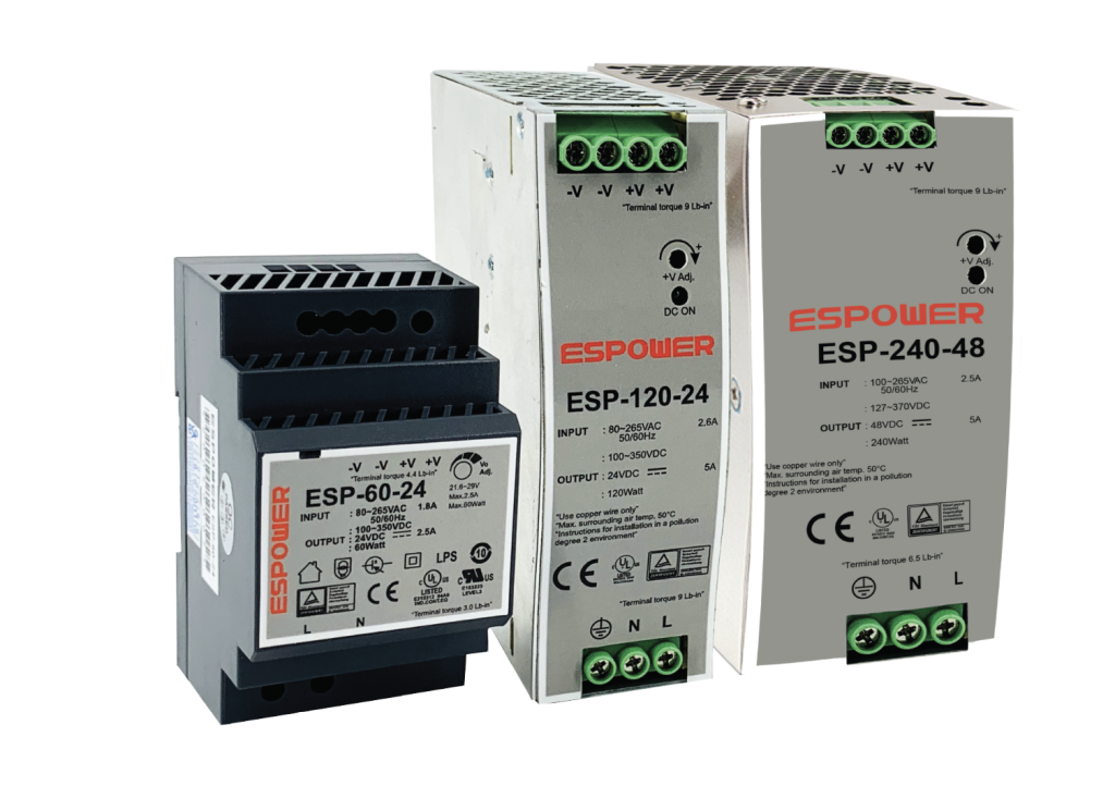
The Power supply unit is a DC/DC converter regulated type, designed with surge protection and to provide transient surge isolation between the station battery and the sensitive electronic components of the annunciator system. Fuse protection is also provided to protect from overload or short circuit on the power supply output. There are three rating : 60 watts, 120 watts and 240 watts to suit for the annunciator system (16, 32, 64 and more alarm point).
Input voltage is 48, 110, 125 or 220 VDC (Specified when order) but output voltage shall be 24 VDC only.
Operating principle
The ESPAN-01 series annunciator system is simple for installation by using detachable connector concept which managed most of the wiring. Besides, it is convenience for maintenance. Only the malfunction module of the three separate- modular module can be repaired or changed.
The operation sequence of the annunciator is as following; when the fault signal is occurred in each input, an alarm output signal is sent toward bell/horn or buzzer which can be pre-selected as heavy fault (Bell/Horn) or light fault (Buzzer). At the same time, it will send flicker output to the set style indication lamp that corresponds to each I/O channel. After pressing an acknowledged push button switch, if an alarm-contact is returned, then the alarm is canceled. However, the indication window is steady on unless the reset push button switch is activated. Then the lamp will be turn off and ready for the next operation.
The lamp test push button switch is also provided for the purpose of checking lamp at normal condition and while checking the lamp, if a fault occurs, the operating alarm sequence will operate as usual with no effect from the lamp test sequence anymore.
Function test of ESPAN-01 Annunciator : if the lamp test push button switch is pressed more than 3 seconds, all the display window lamps would flash with audible sound alarm. (Bell/Horn or Buzzer)
Display windows
• Display window frames are made of alu-zinc steel 1.0 – 1.5 mm. thickness, total depth is not more than 80 mm. (Including protection cover-if any)
• Display window unit is made of self-extinguishing plastic material and acrylic resin for window plate.
• Display window compose of color legend plate, diffused lens and cover lens.
• Number of alarm windows start from 1 to 120 (max. 640 windows)
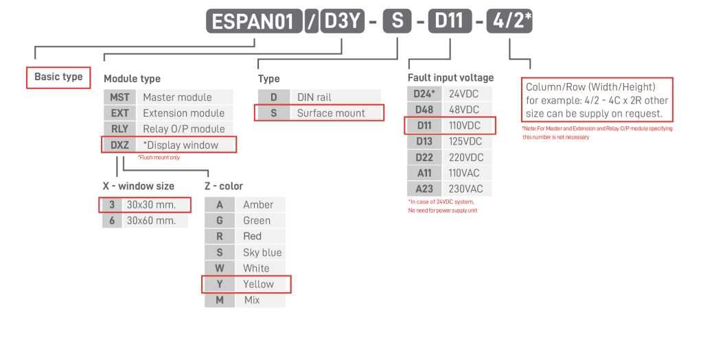
• Window plate color shall be specified when order. W : White, R : Red, G : Green, Y : Yellow, A : Amber, S : Sky blue.
• Window sizes are available in 2 sizes; 30 x 30 mm. and 30 x 60 mm.
• Display lamp is 24 VDC LED; one lamp for window size 30×30 mm. and two lamp for window size 30×60 mm.
• Power consumption : size 30×30 mm. ≤ 0.5W/window, size 30×60 mm. ≤ 1.0W/window
• Lamp replacement could be done easily by taking off the front plate.
• Wiring connection between display window to alarm sequence unit is 1.5-2.5 sq.mm. or up on the requirement.
• Connection to the display windows has to be done through the terminal of the rear side only.
• Window arrangement is flexible according to the requirement (Specified when order)

Dimension
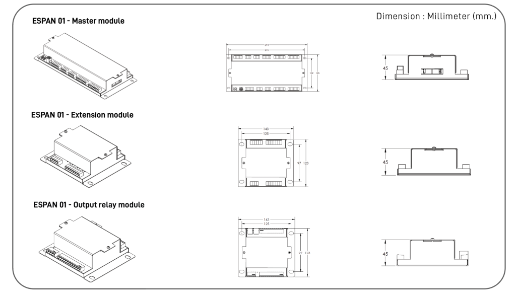
Surface mount type
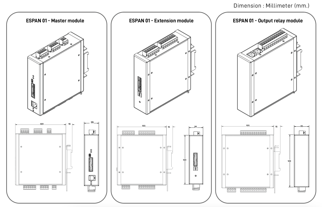
DIN rail type
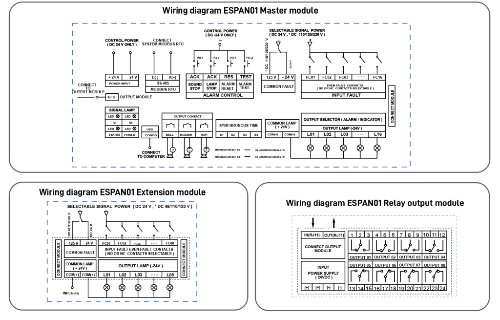
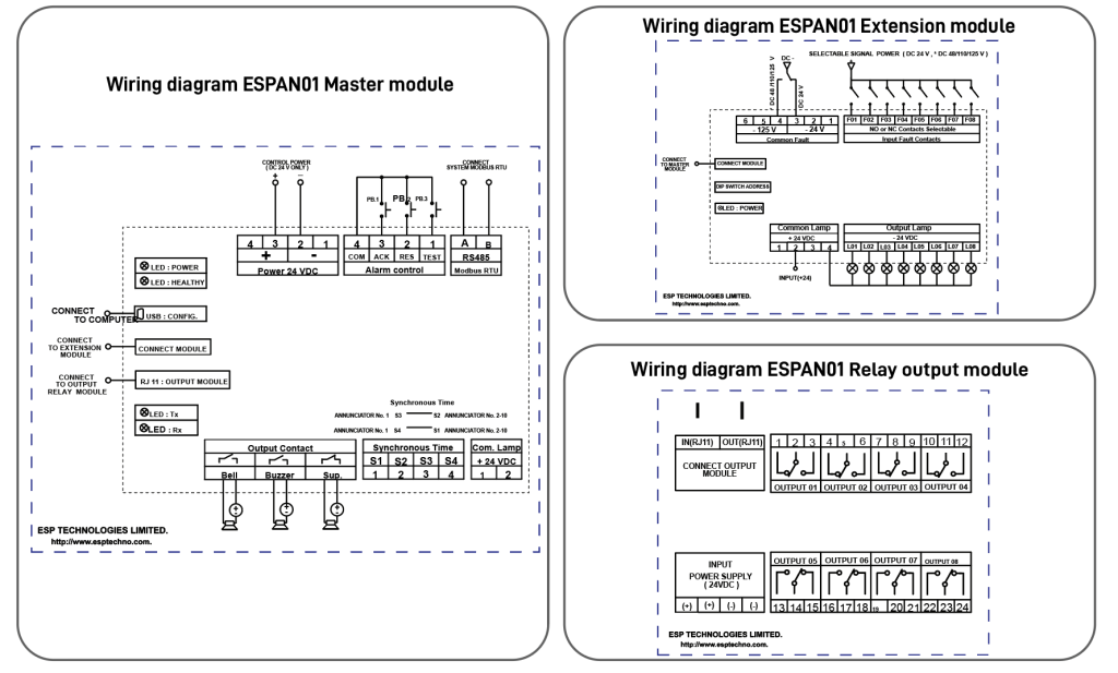
Wiring diagram
Surface mount type
DIN rail type
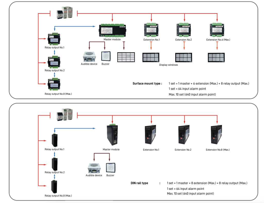
System of annunciator ESPAN 01
Product coding
